| Isometric projection |
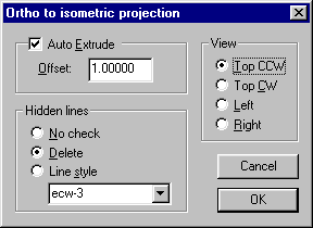
The Isometric projection command will convert a regular 2D-view to an isometric view.
There are four standard methods:
- Top CCW - create top view by rotating the objects counter clock-wise.
- Top CW - create top view by rotating the objects clock-wise.
- Left - create left view.
- Right - create right view.
The projected view can automatically be extruded be enabling the Auto Extrude option. The objects will then be extruded by
the Offset value. The settings on how to process hidden lines are included here as well as in the extrude options dialog.
All entities that support non-uniform transforms in FastCAD will be converted properly. They have to support independent XY-scaling etc.
| Commands: |
| IVIEW |
Create an isometric projection. |
|
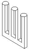
Extrude an isometric view |
The extrude command will extrude an isometric view. The extrude direction will normally lock to every 30ø.
If the SHIFT key is pressed the lock is disabled and you can extrude in any direction.
The extruded object can be analyzed for hidden lines. There are three different actions:
- No check - don't perform any check for hidden lines
- Delete - delete hidden lines
- Line Style - change line style for hidden lines.
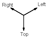
If Delete or Line Style is used the object will be analyzed for hidden lines. If you analyze hidden lines the extrude
direction has to be positive (Positive directions are shown in the figure). Generally the direction is the opposite of the
projected view, i.e. a top view is extruded downwards, a left view extruded to the right etc.
To speed up the hidden line analyze all paths and splines will automatically be exploded to lines in the extruded copy. They still
take some time to process. There is a progress indicator to let you know how long it will take. To speed up things some more explode
the entities to lines before extruding them. Lines are the easiest (and fastest) entities to process.
The hidden line analyze is not perfect, but generally remove most of the unwanted lines. It is then easy to fill in the rest of the
lines using ILINE, LINE, TANGENT, ERASE and TRIM. To analyze hidden lines, there are a lot of intersections to detect. Some intersections are not found due to lack of precision causing a line to get the wrong visibility status.
| Commands: |
| IEXTR |
Create an isometric extrusion |
| IEXTRIN |
Create an isometric extrusion (inside) |
| IEXTROPT |
Settings for the isometric extrusion |
|
Isometric lines |
|
The isometric line command works like the regular line command with a few extra features.
- It will automatically snap to every 30 degrees.
- Instead of endpoint for a line you can enter a length.
The direction currently displayed by the dynamic cursor will be used.
| Commands: |
| ILINE |
Draw an isometric line |
|
Isometric projected circles |
|
The isometric circle commands create circles and then project them to an iso view projection, there they become
ellipses. There are separate commands for top, left and right projections.
| Commands: |
| ICIRT |
Draw an isometric circle, top projection |
| ICIRL |
Draw an isometric circle, left projection |
| ICIRR |
Draw an isometric circle, right projection |
|
Fillet & trim |
There is a fillet & trim command that works in a project isometric view. It works just like the regular FastCAD
fillet & trim command (TFIL), except that the created fillet arc will be an elliptical arc. There are different commands for
the top, left and right projections.
| Commands: |
| ITFILT |
Fillet & trim in a top projection |
| ITFILT |
Fillet & trim in a left projection |
| ITFILT |
Fillet & trim in a right projection |
|
Dimensions |
|
Parallel, radius and diameter dimensions can be created in isometric views. They are created as regular FastCAD
dimension entities.
- You can use the TAB key to toggle the leader angle for parallel dimensions.
- With ortho turned on the commands will snap to every 30 degrees
- Do not stretch the parallel dimensions as FastCAD will deform them if this is done.
Note that due to the nature of isometric drawings parallel dimensions has to be placed along one of the isometric
axis to messure a correct distance.
| Commands: |
| IDIMP |
Parallel dimension |
| IDIMR |
Radius dimension |
| IDIMD |
Diameter dimension |
|
Automatically added menu |
As default a menu is automatically appended. The menu will be placed at the end of the menu bar, just before Help.
If you don't want the menu it can be turned off with the ISOMENUOFF command. The ISOMENUON command will turn it back on again. The state is stored in the registry so the menu will not appear again in the next session.
Both the commands require the menu to be reloaded. This is automatically done when you start a new FastCAD session.
| Commands: |
| ISOMENUOFF |
Turn off the automatic menu. |
| ISOMENUON |
Turn on the automatic menu. |
|
Limitations in the IsoView demo |
As soon as any IsoView command is used save will be disabled for the rest of that
session. A warning will be displayed the first time an IsoView command is used, letting you know that save will be disabled.
The demo has no other limitations.
Download the demo now!
|